Surface Profile Measurement Methods
A practical comparison of comparators, depth micrometers, replica tape and stylus instruments — how each works, what it really measures and how to choose and document the right method.

Key takeaways
- Surface profile can be measured with visual comparators, depth micrometers, replica tape or portable stylus instruments; each samples the surface differently.
- Results from different methods are not interchangeable, so the specification should name one method and its acceptance criteria.
- Readings need to be taken on a representative, clean, blasted surface, at a defined frequency, and recorded with their locations.
- For steel, SSPC-PA 17 sets out how to determine conformance with profile and peak count requirements.
Most coating specifications for blasted steel require a surface profile within a stated range — for example, 2–3 mils (50–75 µm) — because profile height affects adhesion and how much coating is needed to cover the peaks. Why profile matters and what controls it are covered in surface profile (anchor pattern). This article focuses on how profile is measured, how the methods differ and how to avoid disputes over the numbers.
The standards behind the methods
- ASTM D4417 describes three field methods for blast-cleaned steel: Method A (visual comparator), Method B (depth micrometer) and Method C (replica tape).
- ASTM D7127 covers measurement with a portable stylus instrument, reporting profile height and peak count.
- ISO 8503 is a multi-part series: Part 1 specifies ISO comparators for grit- and shot-blasted surfaces, Part 2 the comparator method of grading, Parts 3 and 4 the focusing microscope and stylus procedures used to calibrate comparators and determine profile, and Part 5 the replica tape method.
- NACE SP0287 describes field measurement of profile using replica tape.
- SSPC-PA 17 sets procedures for determining whether measured profile and peak count conform to the specification.
For a wider orientation to these bodies and documents, see SSPC, NACE and ISO surface preparation standards and key ASTM standards for coatings.
Comparing the methods
| Method | What it measures | Strengths | Weaknesses |
|---|---|---|---|
| Visual/tactile comparator | Closest match to reference segments | Fast, no consumables | Subjective; coarse resolution; must match abrasive type |
| Depth micrometer | Depth of individual valleys relative to local peaks | Quick, digital data logging, low running cost | Point readings; sensitive to placement and dust |
| Replica tape | Average maximum peak-to-valley height over a small area | Widely accepted; tape is a physical record | Consumable cost; limited range per tape grade |
| Portable stylus | Profile parameters such as Rt and peak count (Rpc) | Gives peak density as well as height | More expensive; needs care on curved or rough surfaces |
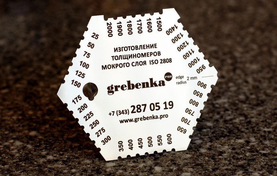
It is normal for replica tape and depth micrometer readings on the same surface to differ. Tape effectively averages the highest peaks and deepest valleys across its window; a micrometer measures individual valleys. Neither is “wrong” — but switching methods mid-job invites disputes.
Visual comparators (Method A)
A comparator is a reference disc or plate with segments of known profile. The inspector places it on the blasted surface and, using a magnifier and sometimes touch, selects the segment that most closely matches. Comparators exist for grit (angular) and shot (rounded) blast patterns; using the wrong one gives misleading results. Comparators are useful for a quick check or as a screening tool but are rarely the sole acceptance method on critical work.
Depth micrometers (Method B)
A profile depth micrometer has a flat base that rests on the peaks and a spring-loaded conical point (typically 60°) that drops into the valley beneath it. Modern digital models store readings and statistics.
- Zero the gauge. Zero it on a smooth reference such as a piece of float glass, and verify it with a reference shim or block as the manufacturer directs.
- Clean the surface spot. Remove loose dust and abrasive so the base sits on peaks, not debris.
- Take a set of readings. Lift and place the gauge at multiple points within the measurement location; do not drag it across the surface.
- Report per the standard. Follow the number of readings and the reporting rule in the edition of ASTM D4417 in force (the method has historically reported the maximum of the readings at each location, after discarding obvious outliers caused by debris).
Inspect the conical point regularly. A blunted or chipped tip cannot reach the bottom of valleys and will under-read, especially on fine profiles.
Replica tape (Method C)
Replica tape is a compressible foam layer on an incompressible polyester backing. Burnished onto the blasted surface, the foam takes an impression of the peaks and valleys; a spring micrometer then measures its thickness, and the backing thickness (commonly 2 mils, 50.8 µm) is subtracted. Grades cover different ranges, so the expected profile determines the tape selected. The stepwise procedure is described in surface profile.
Common errors include burnishing incompletely, measuring on rusted or contaminated spots, using a grade outside its range, and failing to zero or verify the micrometer. Some digital readers measure the tape automatically and log the results, which reduces transcription errors.
Stylus instruments and peak count
A portable stylus instrument drags a fine diamond-tipped stylus across the surface and records a trace. Under ASTM D7127, it reports parameters such as Rt (maximum peak-to-valley height over the evaluation length) and Rpc (peak count per unit length). Peak count matters because two surfaces with the same height can have very different peak density, and a higher peak density generally provides more surface area for adhesion. Some specifications — particularly for thermal spray and some high-performance linings — specify a minimum peak count as well as a height range.
Sampling, conformance and records
A single reading says little about a large structure. Specifications should define the method, the frequency (for example, a number of locations per area or per shift), how readings are combined at each location and what happens when a location falls outside range. SSPC-PA 17 provides a framework for this and for retesting and remediation.
- Measure after blasting and cleaning but before priming, on representative areas — including complex geometry, not just easy flat plate.
- Check profile at the start of the job and whenever the abrasive, blast pressure, nozzle or operator changes (see abrasive media selection).
- Record method, gauge serial number, verification, readings and locations in the inspection report; keep replica tapes when required.
Too much profile can be as harmful as too little: tall peaks may protrude through thin primers and become rust sites. Treat out-of-range high readings as nonconformances, not as a bonus.
Concrete and other substrates
Concrete texture is not measured in mils. It is classified by comparison with the ten Concrete Surface Profile (CSP) chips described in ICRI 310.2R, from CSP 1 (nearly flat) to CSP 10 (very rough). Some inspectors also use laser or optical profilometers for documentation. See concrete surface preparation and CSP. For non-ferrous metals and abrasive-swept galvanizing, replica tape and stylus methods can still be used, but the coating manufacturer’s requirements govern the target range.
Frequently asked questions
Which surface profile method is most accurate?
None is universally “most accurate” — each measures a different aspect of the surface. Choose the method the specification names and use it consistently.
Can I measure profile through primer?
No. Profile must be measured on the bare blasted surface before coating. Once primed, profile can only be estimated destructively.
Why do my replica tape readings vary across a beam?
Profile varies with blast angle, distance, operator technique and steel hardness. Variation is normal within limits, which is why multiple readings and locations are required.
What is peak count and when does it matter?
Peak count is the number of peaks per unit length. It matters when a specification sets a minimum, often for thermal spray metallizing or demanding immersion linings.
Educational reference. Coating performance varies by formulation. Always follow the manufacturer’s product data sheet, safety data sheet and your project specification.