Gloss & Color Measurement
How glossmeters and spectrophotometers turn appearance into numbers — measurement geometries, gloss units, CIELAB and ΔE color difference — and how to use them for matching and weathering.
Key takeaways
- Gloss is measured in gloss units (GU) at 20°, 60° or 85°; start at 60° and switch to 20° for high-gloss or 85° for low-gloss finishes.
- Color is measured with a spectrophotometer or colorimeter and expressed in CIELAB coordinates; the difference between two colors is reported as ΔE.
- Instrument geometry, illuminant, observer and ΔE formula must all be stated, or numbers from different labs and instruments will not agree.
- Instruments complement the eye. Metamerism, texture and lighting still require a controlled visual check.
Appearance matters on architectural steel, equipment, flooring, vehicles and anything a customer sees. It also matters as a performance indicator: loss of gloss and color shift are often the first visible signs that a coating is degrading. Gloss and color measurement give specifiers, applicators and manufacturers a common, objective language for describing appearance, setting tolerances and tracking change over time.
Measuring gloss
Gloss is the ability of a surface to reflect light in a mirror-like (specular) direction. A glossmeter shines a light beam onto the surface at a fixed angle and measures how much is reflected at the equal and opposite angle. Readings are reported in gloss units (GU) relative to a polished black glass reference standard. ASTM D523 and ISO 2813 are the main standards for specular gloss of coatings.
Choosing the geometry
Three geometries cover most coatings. The 60° geometry is the general-purpose starting point. If a 60° reading is high (commonly above about 70 GU), the 20° geometry gives better resolution between high-gloss samples. If it is low (commonly below about 10 GU), the 85° geometry better distinguishes matte and flat finishes. Always report the angle with the value: “85 GU” means little without it.
| Geometry | Best for | Typical use |
|---|---|---|
| 20° | High-gloss finishes | Topcoats, automotive, polyurethanes |
| 60° | Mid-range; general screening | Most industrial and architectural coatings |
| 85° | Low-gloss, matte and flat | Flat architectural paints, matte finishes |
Gloss category names such as “flat,” “eggshell,” “satin,” “semi-gloss” and “gloss” are not standardized across manufacturers, so specifications should state a numeric range and geometry rather than a word alone.
Beyond simple gloss
Two surfaces with the same 20° gloss can look different because of haze or texture. Haze, distinctness of image and texture measurements are used in automotive and high-end finishing, where effects such as orange peel matter as much as the gloss number.
Measuring color
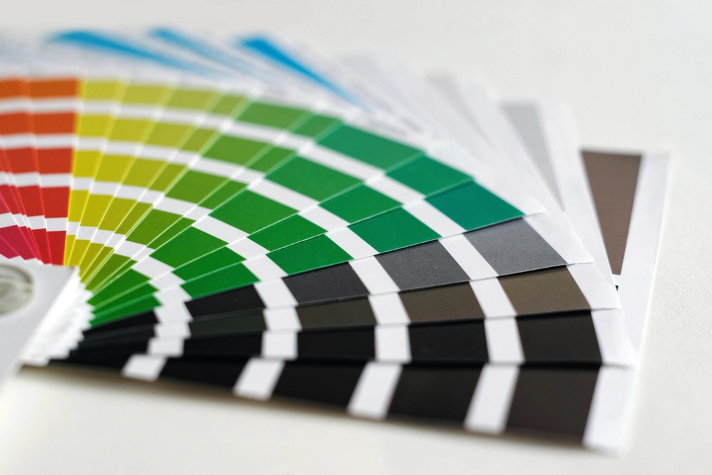
Color instruments measure how much light a surface reflects at each wavelength across the visible spectrum. Spectrophotometers record the full reflectance curve; colorimeters use filters that mimic the eye’s response and are simpler but less versatile. Software then calculates color coordinates for a chosen illuminant and observer, following methods such as those in ASTM E308.
CIELAB coordinates
Most coatings work uses the CIELAB color space, which describes color with three values:
- L* — lightness, from 0 (black) to 100 (white).
- a* — red (positive) to green (negative).
- b* — yellow (positive) to blue (negative).
A positive Δb* on a white topcoat after exposure, for example, indicates yellowing; a rise in ΔL* on a dark color often accompanies chalking and fading.
Instrument geometry
Color instruments use either directional geometry (45°/0° or 0°/45°), which sees color roughly as the eye does under directional light, or a sphere geometry (d/8°), which can include or exclude the specular reflection (SCI or SCE). Glossy and matte samples of the same pigment can read differently on different geometries, so the geometry should be fixed in the specification.
Color difference and tolerances
ASTM D2244 covers calculating color differences from instrumentally measured coordinates. The simplest formula, ΔE*ab, is the straight-line distance between two points in CIELAB space. Because the eye is more sensitive to some differences than others, newer formulas such as CMC and CIEDE2000 (ΔE00) weight the components to better match perception.
Tolerances depend on the product, the color and the customer. Very tight tolerances, often around 1 ΔE unit or less, are common for adjacent panels and parts that must match; looser tolerances may be acceptable for industrial equipment or touch-up. Agree the formula and limits before production — a value of 1.0 in ΔE*ab is not equivalent to 1.0 in ΔE00.
Two samples can match under daylight and mismatch under warehouse or store lighting if they were made with different pigments. Check matches under more than one illuminant, and avoid substituting pigments in touch-up material without a metamerism check.
Visual assessment
Instruments do not replace trained eyes. ASTM D1729 covers visual appraisal of colors and color differences of opaque materials under controlled lighting and viewing conditions. A light booth with standardized sources (daylight, incandescent and fluorescent or LED) allows quick checks for metamerism. Visual checks are also essential for effect finishes such as metallics and pearlescents, which change appearance with viewing angle and need multi-angle instruments for objective measurement.
Good measurement practice
- Calibrate. Calibrate glossmeters on their reference tile and color instruments on their white and black standards at the start of each session.
- Prepare the surface. Measure clean, dry, fully cured surfaces; wipe off dust and fingerprints without polishing.
- Take multiple readings. Average several readings at different spots and orientations, especially on textured or brushed surfaces.
- Control the sample. Use flat, rigid panels of known film thickness when comparing batches or weathering results.
- Record settings. Note geometry, illuminant, observer, formula, instrument and cure age with every result.
Keep a retained, unexposed panel of every approved color and gloss standard in a dark, cool place. It gives you a physical reference for future batch approvals, touch-up and disputes.
Using gloss and color in weathering and specifications
Gloss retention and color change are the most common pass/fail measures in accelerated weathering and outdoor exposure programs. Results are usually reported as percentage gloss retention relative to the initial reading, and as ΔE or individual ΔL*, Δa* and Δb* changes. Topcoats with strong ultraviolet resistance, such as fluoropolymer coatings, are often specified on the basis of long-term gloss and color retention data.
When writing a specification, state the property, the geometry or instrument settings, the target, the tolerance and how many readings make up a result.
Frequently asked questions
What angle should I use to measure gloss?
Start with 60°. Use 20° if the 60° reading is high and 85° if it is low, and always report which angle you used.
What is a “good” ΔE?
It depends on the application and formula. Tight tolerances for matching parts are often around 1 unit or less, but the limit should be agreed between supplier and customer for each product.
Why do two instruments give different color readings?
Differences in geometry, aperture size, specular handling, calibration and sample presentation all affect readings. Compare results only from instruments set up the same way.
Does film thickness affect gloss and color?
Yes. Low film thickness can let the substrate or primer show through and change color, and application defects affect gloss. Measure at the specified film thickness.
Educational reference. Coating performance varies by formulation. Always follow the manufacturer’s product data sheet, safety data sheet and your project specification.